Profiles 101
Cutting profiles are needed in almost all projects. In Civil 3D, you can view horizontal information in the form of a vertical profile. Today we are going to learn how to:
Generate a profile from an existing alignment
First, an alignment and surface is needed before creating a profile. Once the alignment is ready, it is time to create the profile.
Menu > Profiles > Create Profile from Surface.

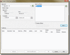
“Create Profile from Surface” box pops up. This is where the profile object information (existing surface) is added to the profile view information (grid, station labels, etc). Under Alignment, select the alignment to profile.
Once you select the surface, click on “add” to place the information in the profile list.
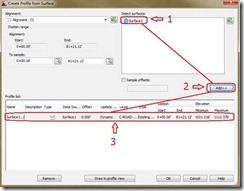
Tip: Profile object information can be added and removed by using the same steps above without recreating the profile.
Tip: When the profile is generated, it is helpful to check the style used for the profile object information.

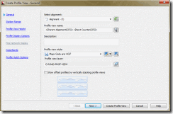
Once all proper information is placed, click on “Draw in profile view” button. A new box will pop up when creating a new profile. The settings are divided into categories:
General:
Select alignment: The alignment in which to create the profile
Profile view name: Give it a name everyone will understand
Description: Remember to add today’s date here
Profile view style: Standard Style set by your CAD Manager
Profile view layer: allows layer to be changed of profile element
Show offset profile box: If you have offsets in your profile, this will place it in different profiles instead of the same profile.
Station Range:
Automatic: This will automatically set up the station range for the profile
User specified range: Customize the station range of the new profile
Profile View Height:
Automatic: Automatically sets elevation range
User specified: Customize the elevation range of the new profile
Split Profile View: Refer to help menu
Profile Display Options:
Same as the profile list in last “Profile View” box
Pipe Network Display:
Pipe information for the profile can be added
Data Bands:
Data Bands are information which can be placed in the profile such as the existing and proposed surface, pipe information, etc. The data bands can be placed at the top or the bottom of the profile.
Selection Band Set: Selection of the type of data bands needed
Location: Location of bands (top or bottom)
Set band properties: Setting per design.
Profile Hatch Options:
Hatch can be added to areas within the profile.
Once setup is complete, click “Create Profile View.” The software will prompt for the location of the profile. Select the location in the drawing in which to place the profile.
Changing profile styles and editing profiles properties
Profile properties can be modified at any time after creating the profile by:
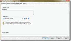
Clicking on the Profile > Right Click > Profile View Properties
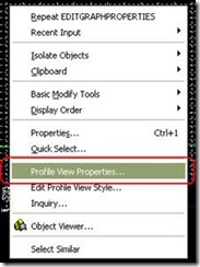
After a profile has been generated, information can be edited as if you were creating a new profile.
- Generate a profile from an existing alignment
- Changing profile styles and editing profile properties
Generate a profile from an existing alignment
First, an alignment and surface is needed before creating a profile. Once the alignment is ready, it is time to create the profile.
Menu > Profiles > Create Profile from Surface.

“Create Profile from Surface” box pops up. This is where the profile object information (existing surface) is added to the profile view information (grid, station labels, etc). Under Alignment, select the alignment to profile.

Once you select the surface, click on “add” to place the information in the profile list.

Tip: Profile object information can be added and removed by using the same steps above without recreating the profile.
Tip: When the profile is generated, it is helpful to check the style used for the profile object information.

Once all proper information is placed, click on “Draw in profile view” button. A new box will pop up when creating a new profile. The settings are divided into categories:
- General
- Station Range
- Profile View Height
- Profile Display Options
- Pipe Network Display
- Data Bands
- Profile Hatch Options

General:
Select alignment: The alignment in which to create the profile
Profile view name: Give it a name everyone will understand
Description: Remember to add today’s date here
Profile view style: Standard Style set by your CAD Manager
Profile view layer: allows layer to be changed of profile element
Show offset profile box: If you have offsets in your profile, this will place it in different profiles instead of the same profile.
Station Range:
Automatic: This will automatically set up the station range for the profile
User specified range: Customize the station range of the new profile
Profile View Height:
Automatic: Automatically sets elevation range
User specified: Customize the elevation range of the new profile
Split Profile View: Refer to help menu
Profile Display Options:
Same as the profile list in last “Profile View” box
Pipe Network Display:
Pipe information for the profile can be added
Data Bands:
Data Bands are information which can be placed in the profile such as the existing and proposed surface, pipe information, etc. The data bands can be placed at the top or the bottom of the profile.
Selection Band Set: Selection of the type of data bands needed
Location: Location of bands (top or bottom)
Set band properties: Setting per design.
Profile Hatch Options:
Hatch can be added to areas within the profile.
Once setup is complete, click “Create Profile View.” The software will prompt for the location of the profile. Select the location in the drawing in which to place the profile.
Changing profile styles and editing profiles properties
Profile properties can be modified at any time after creating the profile by:
Clicking on the Profile > Right Click > Profile View Properties

After a profile has been generated, information can be edited as if you were creating a new profile.
